So You Want to Design a Pintle Injector: Version 1
So You Want to Design a Pintle Injector
An Introduction and Background
(and way more details on how I designed an injector than you probably ever need, and yet, probably not enough details, all in the the context of a random rocket engine’s development)
By Max Oberg
Warning: Units are everywhere at times. I may be referring to kg in one section, and lbs in the next. I wish it wasn’t this way, but I am slightly lazy, and someone decided to ignore the French in the 1800s and now it’s out of my hands. (Also, screw you 1950s paper on annular orifice discharge coefficients specifically).
Note: Any mention of “Herald” is referencing the original engine this injector was designed for, which was designed and developed by the PARSEC team at Caltech.
Nomenclature
Now, no paper with formulas should ever, in my opinion, be without this handy table below. I get so annoyed reading papers that assume I inherently understand the variables they picked. I am monkey who barely remembers to brush his teeth at night, If I am trying to learn from your paper, please don’t make it harder than it needs to be.
| Variables | Subscripts |
|---|---|
| $\dot{m}$= Mass Flow Rate | exp = Expected |
| $\rho$ = density | ideal = Value Dealing with Ideal Flow |
| $u$ = velocity | fuel = Value Dealing with Fuel Characteristics |
| $C_d$ = Discharge Coefficient | ox = Value Dealing with Oxidizer Characteristics |
| V̇ = Volumetric Flow Rate | oa = Outer Annular Orifice |
| A = Area | |
| $\Delta P$= Pressure Difference/Stiffness | |
| N = Number of Central Pintle Shaft Orifices | |
| d = Diameter | |
| BF = Blockage Factor |
This small table below are variables specific to the 1950s paper found in the above Warning above. Whether this paper is strictly necessary is definitely up for debate, however, I leave it here anyway.
| 1950s Discharge Coefficient Paper Terms Below |
|---|
| G = Mass Flow Rate Through an orifice (ṁ/A) |
| μ = Fluid Absolute Viscosity |
| $C_c$ = Coefficient of Stream Contraction in an Orifice |
| F = Fraction of maximum pressure recovery due to stream expansion from the vena contracta to full annulus area actually recovered in an orifice (a hell of a mouth full, I know) |
| $𝑓_𝑝$ = Friction Factor for Flow Between Parallel Plates of Infinite Width |
| Z = Concentric Annular Length-to-Width Ratio |
| L = Orifice Thickness/Length |
Now, most if not all of the above terms will be described in due time, never fear!
Introduction
Every rocket engine will typically have a few preset parameters before you approach the design of an injector. Among these are:
-
Fuel and Oxidizer choice
-
Mixture Ratio
-
Mass Flow Rates of Propellants
-
Chamber Pressure of the Rocket Engine
Before we use these values however, some aspects of fluids needs to be discussed.
Injectors on a fundamental level are plates of metal with holes in them. Your shower head? An injector. Your sink faucet? An injector. Your sunscreen bottle? Yes, also an injector. So the basic question you must ask first when approaching the design of the injector, is how big should the holes in question be?
With a certain set mass flow rate, density, and injection velocity, one can begin to calculate an ideal area for which the holes (or orifices) should be ideally size. This equation can be seen below:
\[Area = \frac{\dot{m}}{\rho \cdot u} \tag{1}\]Now, there are some broad assumptions you are making to use the above equation (This equation is a conservation of mass equation, with the assumption that there is Steady, Uniform, and Incompressible flow). However, when fluid flows though an orifice, the effects of boundary conditions around the flow (the “walls” and edges of the hole/orifice), as well as entry/exit conditions (feed pressure, exit pressure, whether the hole is a sharp edge or rounded) cause the ideal mass flow rate ($\dot{m}$) above to not accurately reflect reality. This results in a lower mass flow rate through the orifice than originally calculated. We call the ratio between the ideal flow and the actual flow the Discharge Coefficient.
\[C_d = \frac{Q_{\text{exp}}}{Q_{\text{ideal}}} \tag{2}\]The discharge coefficient is the ratio of the expected flow over ideal flow. For circular orifices, the simplified equation below is sufficient to represent the discharge coefficient.
\[C_d = \frac{\dot{m}}{\rho \dot{V}} = \frac{\dot{m}}{\rho A u} = \frac{\dot{m}}{\rho A \sqrt{\frac{2 \Delta P}{\rho}}} = \frac{\dot{m}}{A \sqrt{2 \rho \Delta P}} \tag{3}\]The Wikipedia page for the equation above
A few assumptions must now be made to make forward progress using equation 3. In order to find A (the orifice area), an assumption for $C_d$ and an ideal $\Delta P$ value must be used. A $C_d$ for a circular orifice here can be assumed to be around .61 to start (an estimate based on previous experimental experience). The $\Delta P$ however, is more complex.
$\Delta P$ is more typically called the Stiffness when dealing with injectors. The stiffness is the difference in pressure across the injector. More specifically, it is the difference between the combustion chamber pressure and the pressure in the main manifold* on the injector (on the other side of the injection orifice).
*a manifold in this sense is a volume for fluid to fill and exists for 2 main reasons. The first is to remove fluid flow affects from the small channels feeding into the injector. So instead of dealing with 48 separate flows, you can treat the fluid being injected into the rocket engine as if its coming from, in essence, a reservoir or tank. The second is to better flow fluid across the back of the injector face in order to cool it.
Typically this value is around 20% for early rocket injectors, before they can be dialed into a lower % with testing. One of the primary reasons you want your injector to have a certain level of stiffness is to avoid any backflow. This occurs when the propellant flow reverses across the injector, and propellant stops being injected to be combusted. Combustion gasses potentially turning your injector manifold into a new combustion chamber is, to say the least, not great!
Additionally, if the stiffness is sufficiently low, a pressure wave could momentarily reverse the flow in the injector orifices. This causes an interruption to any propellant injection, and a momentary interruption to the combustion. This is a phenomenon known as Chugging. This typically will result in an oscillation in the chamber gases, that can severely affect your performance/controllability, and worse case scenario: destroy your engine. Further complications to stiffness in an engine arise when you throttle the engine.
Throttling
When an engine is deigned to throttle, the mass flow rate is the variable that we are changing. This is done by 3 main methods:
1) Upstream propellant throttling
You can throttle a rocket engine by using a valve in the propellant feed system to change the mass flow rate that feeds the engine. A few rules of thumb for this “fixed area throttling” (not a super official term, but it is an important distinction), is that mass flow rate varies linearly with thrust, while pressure drop ($\Delta P$) changes as the square of flow rate. For example, a 50% reduction in thrust results in a drop from an an example 200psi $\Delta P$ to 50 psi $\Delta P$.
For the fixed injector version of Herald, the engine is designed to throttle to 40% of its maximum thrust. As such, with an initial stiffness of 30% at maximum thrust, the stiffness at minimum thrust will be 12%. The 40% goal is only an ideal test stand target, but operationally the plan was to only use the engine down to 50% thrust in flight. Tuning the engine and figuring out what its true lowest operational stiffness can be is something that would be figured out once the engine was hot fired
author’s note, I’ll add examples of this in use in specific rocket engines in the future
2) Neutral gas Injection
This method involves injecting a neutral gas into the combustion chamber to decrease the engine’s combustion efficiency. This gas is typically inert, such as nitrogen. However, in a vehicle’s design, one might use whatever gas is being used to pressurize the tanks, which is typically nitrogen or helium.
repeat of the above note
3) Variable Area Throttling
The third option to throttle a rocket engine is by varying the injection orifice area to effectively change the mass flow rate at the point of injection. This makes an inherently more complex engine and injector, however, this gives you two significant advantages. The most significant one is the throttle range possible with the engine.
By changing the injection orifice areas, and not the feed pressure (as in type 1), you will be able to maintain a much higher stiffness value at much larger throttle percentages. This means for engines that need to perform complex maneuvers, having the capability to deep throttle is vital. This type of injector was developed and put to use on the original Apollo Lunar Lander vehicle. The second advantage is the response time to throttle input. An upstream restriction on the propellant will take a measurable amount of time before a similar reduction in thrust, however, by throttling at the moment of injection, the response should be nearly instantaneous. This third throttling type leads us to, finally, the Pintle Injector
Pintle Injector
According to all known laws of rocket science, the pintle injector is hands down the best injector of all time and nobody disagrees. We will be ignoring all claims otherwise and proceed with said pintle injector description now.
The pintle injector was first developed at JPL in the midst of the rocket renaissance in the 1950s. The design would then get further developed by TRW over the next 30 years until it was acquired by Northrup in 2002 (the TRW sources about this injector also sort of just, stop, after this point. The amount of information on the internet lost due to company mergers like this is terrible. Aerojet Rocketdyne’s website information is the same way). Perhaps the most famous use of the pintle injector was on the Lunar Module Descent Engine (LMDE) and on Space X’s Merlin engines.
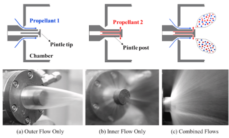
The pintle functions with two main components, the manifold body, and the pintle shaft. Propellant 1 is injected via an annular (circular) gap around the outside of the pintle shaft. This creates (typically)$^1$ a circular sheet flowing towards the rocket engine’s throat/exit. Propellant 2 is injected via holes or slots (typically)$^2$ perpendicular to the flow of propellant 1. The two propellants will then impinge and mix, as shown in Figure 1 below.
1 - Pintle annular orifices could also be a circle of distinct orifices so instead of one contiguous sheet being injected, its N number of holes injecting down the shaft.
2 - This will be covered a little later, don’t worry
As much as the pintle is always the best injector, it may need some further justification. The pintle injector was chosen for the Herald engine (the PARSEC/Caltech engine) for a few different reasons. The first is ease and simplification of manufacturing. Avoiding the drilling of holes at unique angles in an injector face (such that streams of propellant impinge directly as in an impinging doublet injector), or drilling a lot of holes was ideal. Furthermore, creating a single injector body, then varying the diameter of the central pintle shaft to control Propellant 1 injection area allows a bit of flexibility in the design. This allows any future iterations to our design to be much simpler and cheaper to iterate by simply creating a new pintle shaft (assuming there isn’t a fundamental issue with the initial manifold body, or that any necessary changes would change the manifold body design)
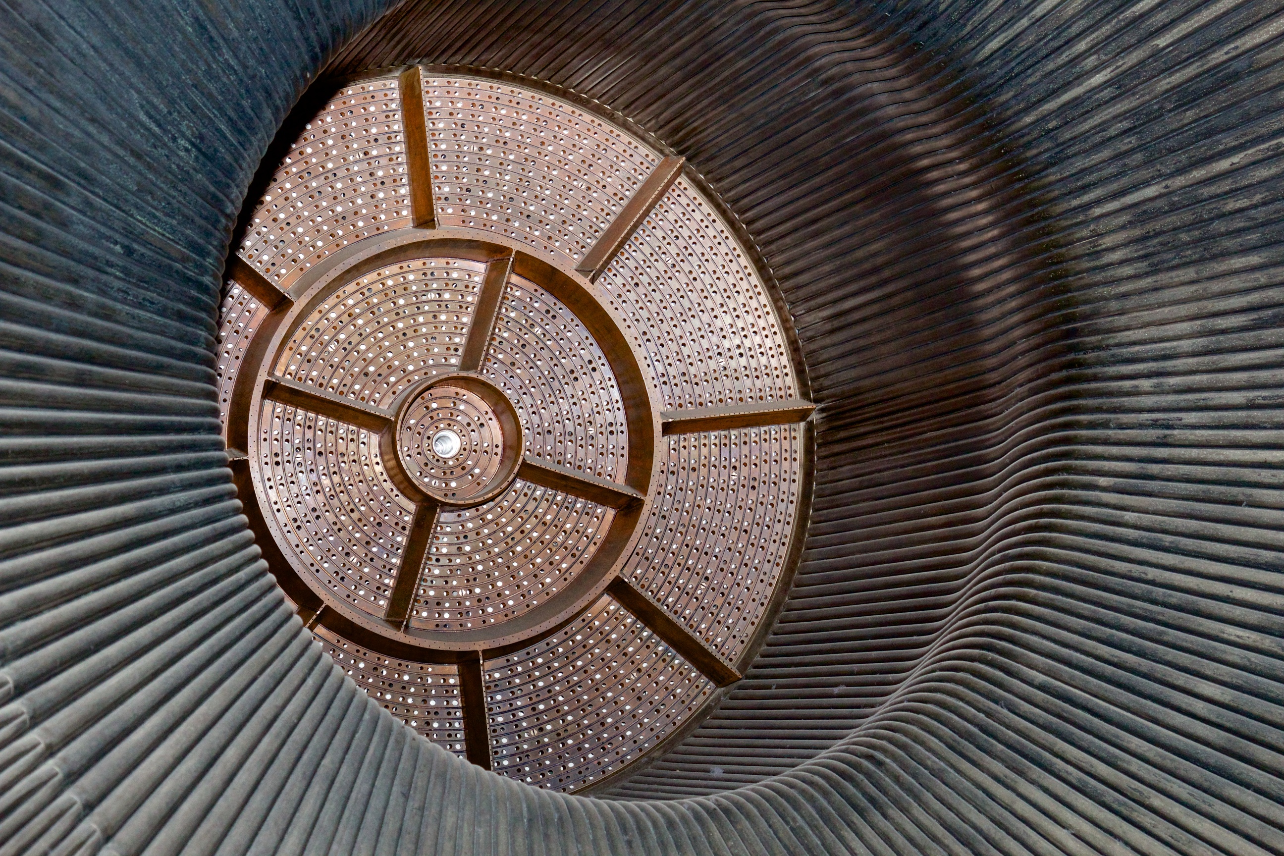
A slightly lesser reasons, but worth mentioning, is the combustion stability of pintle injectors. At the size of Herald (3-4ish inch in diameter), this isn’t too applicable as combustion instabilities generated from other injector designs likely won’t affect this small of engine types. However, in larger engines, it is very much a concern. In the F-1 rocket engine (Which powered the Saturn V and Apollo missions), baffles were added into the injector plate to avoid just such instabilities. These can be seen below in Figure 2.
It is worth mentioning that the pintle was also chosen due to recommendation from alumni and advisors to the PARSEC group. There also existed some design heritage within the club from a previous engine named Valkyrie.
Now, so far in this, whatever this is, I have only made mention of propellant 1 and propellant 2. This is because pintles can be designed to have either the oxidizer or fuel as its central propellant. There are pros and cons to both configurations.
- Oxidizer vs Fuel centered
Herald is regeneratively cooled engine which uses Jet-A as its fuel, and liquid Oxygen (LOX) as its oxidizer. Jet-A flows through cooling channels around the engine to feed the injector from all sides. As such, directing this flow across the injector manifold and down the center pintle shaft, while allowing a separate LOX feed to go around the Jet-A flow and be injected around the pintle shaft adds undue complexity.
However, there are a few draw backs to a lox centered design. If the momentum ratio for the fuel and oxidizer streams is off, the oxidizer stream could break through the injected fuel sheet/streams and directly imping on the walls of the combustion chamber. This could lead to localized hot spots and eventually engine failure. The plan was for Herald’s injector to go through extensive flow testing to confirm the injection pattern characteristics and to avoid this situation as much as possible. Additionally, with lox flowing down the central shaft at a temperature of around 117k, and Jet-A’s freezing point of around 226K, there is a potential risk of Jet-A freezing (how real of a concern this is the I am not sure).
Nitty Gritty
So, now you understand the basics of the pintle, and how the discharge coefficient works. But, how does that affect our pintle design? It should be noted, this section starts to get into rules of thumb, and values that sometimes aren’t very heavily justified. Often this is general advice given to people from TRW engineers who tested this privately back in the day.
The first detail of note is the momentum ratio. As alluded to in the introduction, the momentum ratio heavily affects the amount of area of propellant injection. NASA and TRW’s experience with pintle injectors indicates that a momentum ratio near 1/1 is best for mixing4. That is, the two impinging streams of propellants should impinge at a resultant 45 degree angle. This equation is shown below.
\[\frac{(\dot{m}_{fuel} u_{fuel})}{(\dot{m}_{ox} u_{ox})} = 1 \tag{4}\]The next value of note is the blockage factor (BF). The blockage factor is the total hole length in the circumferential length over the circumference of the pintle shaft (word vomit a small amount). The equation for a number (N) of circular holes (of diameter $D_ox$ is shown below in equation 4.
\[\frac{Nd_{ox}}{\pi d_p} = BF \tag{5}\]As the blockage factor decreases, mixing from direct collisional mixing decreases, and interfacial (or shear) mixing increases. It is specifically mentioned in a Penn State study on pintle injectors that TRW has a history working with injectors with BFs between .3 and .74.
Blockage factors will vary between different designs of pintle injectors based on the setup of the pintle shaft. If a pintle shaft is created in the vein of Figure 1’s pintle, the the blockage factor will be very high if not 1 (a single circular slit for propellant 2). However, in designing Herald’s injector, we tried to keep the complexity of our system low by keeping the pintle shaft to a single element.
When it comes to the number of holes made in the pintle shaft, a rough estimate of 20-36 slots is what has been found to work well (also from the same Penn State study4 based off of TRW engineer advice). However, trying to maximize collisional mixing (direct propellant 1 on propellant 2 mixing), maximizing B, and keeping in mind material properties so injection orifices hold up to the forces within the combustion chamber should be balanced out to whatever is optimal and maximizes the above values. Mixing can be tested via flow tests with prototypes before any hot fires.
The ratio of the diameter of the chamber to the diameter of the pintle is shown as the diameter ratio. This ratio is typically around 3-5 (also also sourced from the Penn State study4).
Finally, the skip ratio is the length from the injector face to the perpendicular injection point (the lox injection holes in Herald’s design) over the diameter of the pintle shaft. This essentially dictates how far into the chamber the pintle shaft reaches. This value should also be around 1. (And by golly wouldn’t ya know it, its from the same….damn….source4)
There are multiple other papers that are helpful and good material for reading more about pintle designs which I will cite here and link in the sources section below.7 - 8 - 9 - 10 - 11
The dynamics of the pintle injectors cause the circulation zones indicated in figure 3 below.
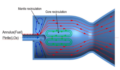
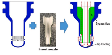
Now, I bring this up for two reasons, the circulation zones indicated above could add to the pintle’s stability mentioned earlier in this article. It could also create complex thermal loads in the pintle tip. There have been some studies done on trying to better cool the pintle tip. Some designs to increase cooling add extra structure on the internal tip to create better circulation as seen in Figure 4.
Now, the one part of this I have not mentioned yet is the size of the annular injection orifice (the fuel injection orifice in Herald’s case). This opens a slight can of worms in my humble opinion/research. The discharge coefficient mentioned earlier in this article specifically applies to circular holes only. So how does this equation change for annular orifices? The answer? Not nicely.
There does not appear to be a nice equation as there is for circular orifices. Some of the most recent work done for those orifice specifically can be found in papers form the 1950s. The most recent I found was from 1989. The 1950 paper’s annular tests seems most similar to pintle annular orifices in terms of sizing and pressure environments. Now, before I go into too much detail here, the end results for the sizing of the annular orifice doesn’t change much from an ideal flow area calculation mentioned in the introduction (by only about 2mm$^2$ for Herald specifically). But damnnit, I did way too much work to get info from this paper to leave it unmentioned. So I give you:
The Nitty Nitty Gritty
The Herald Specifics
(and potentially skippable depending on the audience here)
and I’m really sorry about the units
Herald/Herald’s injector was designed with the following stats:
| Detail: | Value: |
|---|---|
| Maximum Thrust | 610lbf |
| Fuel | Jet-A |
| Oxidizer | Liquid Oxygen (LOX) |
| Fuel Mass Flow Rate | .48 kg/s |
| Oxidizer Mass Flow Rate | .755 kg/s |
| Total Mass Flow Rate | 1.1631 kg/s |
| Minimum Throttle | 40% (244 lbf) |
| Chamber Pressure | 300 Psi |
| Stiffness at Max Thrust (fixed injector) | 30% (90 Psi) |
| Blockage Factor | .58 |
| Diameter Ratio | 5.05 |
The first calculations done were around the lox shaft hole sizing. A number of 28 orifice holes was arrived at (some napkin calculations were done looking at the amount of material that would be between two holes on the inside of the pintle shaft. A minimum of 1 mm of material between each hole was set)
I then divided the mas flow rate by the number of channels to get a per orifice \dot{m} value, and then using the discharge coefficient equation, the area/diam of each lox channel was found to be $1.1857mm^2$/$1.2287mm$. The same stiffness (or $\Delta P$) was used for both fuel and oxidizer orifices. This isn’t strictly necessary, however, it means that any “funky” combustion behavior will affect fuel and oxidizer injection equally (theoretically? I’m rereading this a few months on from originally writing this and questioning the validity of my “justification”). It also simply worked out well for some rough goals of injection velocities so, we’ll take the wins we can here.
The injection velocity was then found using the equation below (a manipulated version of equation 1):
\[\frac{\dot{m}_{ox}}{\rho_{ox} A} = U_{ox} \tag{6}\]The value turns out to be around $20.31 m/s$. This should be a good injection velocity (I’ve seen sources cite ranges of 20-50 $m/s$ as somewhat typical injection velocities (CITATION NEEDED). Keep in mind, there is a balance of injection velocity and chamber length occurring here. If the propellant does not have enough time to fully burn before its velocity carries it out of the chamber, you’ve got a pickle (and an underperforming engine). If you inject to slowly however, you’re leaving potential performance on the table).
So now that we have $\dot{m}$ and $u$ for our oxidizer, and an $\dot m$ for our fuel, we can use the momentum ratio to figure out the needed injection velocity of our fuel (remember, we are trying to shoot for a momentum ratio of 1). This leaves us with a needed fuel injection velocity of about $37.57 kg/s$ of fuel.
Now, later on when finding the correct area of fuel injection , we will need an initial guess. To arrive at a good initial guess, we’ll do the ideal calculation for the area from the values we already have. This is shown in equation 7 below. This gives us an area of about $13.41mm^2$.
\[\frac{\dot{m}_{fuel}}{\rho_{fuel} u_{fuel}} = Area \tag{7}\]Different regimes for annular orifice discharge coefficient calculations are discussed in the 1950s paper. It relies heavily on the Reynold’s number defined as in equation 8 below.
\[Re = \frac{(d_{oa} - d_p)G}{\mu} \tag{8}\]Using equation 7’s estimate for $d_{oa} - d_p$, finding the value of G for that same area (the mass flow rate through an orifice, \(\frac{\dot{m}}{A}\)), and using .00043 ($kg/m/s) as the fluid absolute viscosity, a Reynolds number of a little greater than 30,000 was found. So in the case of a heavily turbulent, concentric annular orifice with square edges, regime E from the paper applies. Regime E is below in equation 8. Z is defined by equation 10.
\[\frac{1}{C_a^2} = \frac{1}{C_c^2} - [\frac{2}{C_c} - 2]F + 2f_p Z \tag{9}\] \[Z = \frac{2L}{d_{oa} - d_p} \tag{10}\]It is expressed in the paper that where $F=0$ for $Z<1.15$, and $F = 1 - e^{-.95(Z - 1.15)}$ for $Z>1,15$. Since our Z value is around 4 (assuming a thickness of around 1mm), the latter is the situation we will implement. Values of $C_C$ and $f_p$ are found from the two figures below respectively (both taken from the 1950s paper).
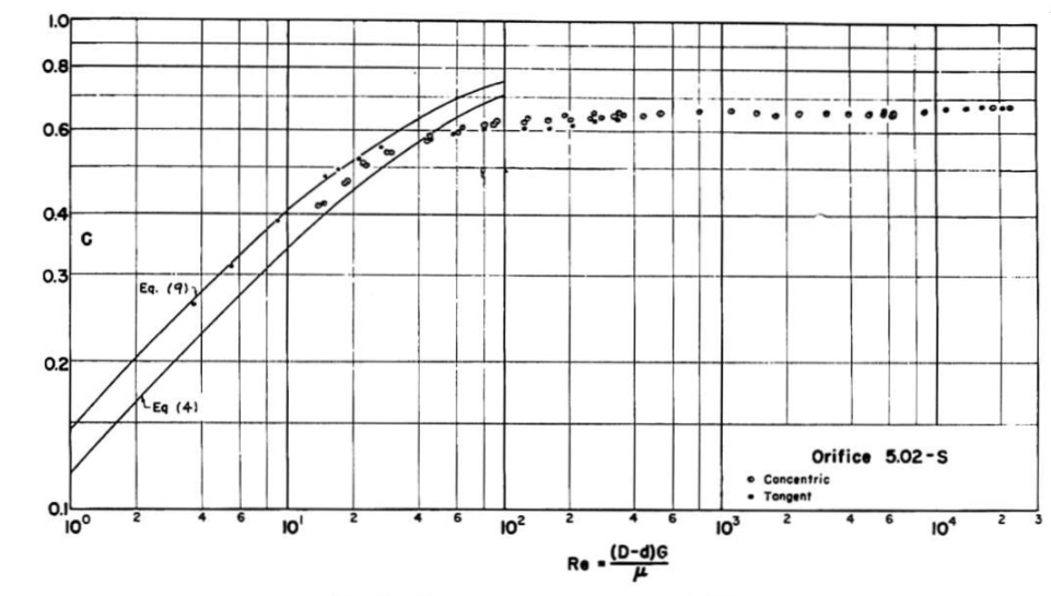
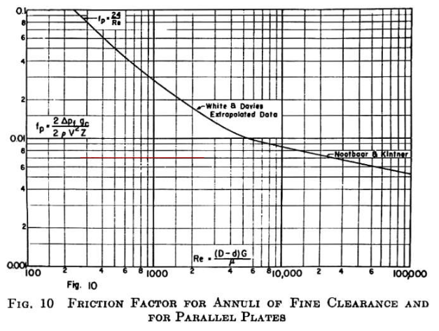
Of note in these figures is that they are both functions of Reynolds number. In order to implement these into my code, I manually picked out values on the graphs for Reynolds numbers of 30,000.
The function I created to size the annulus orifice first calculates the $c_d$ value for the ideal/initial sizing estimate. Then, using that cd value, finds a new ideal area. In this process it calculates the Reynolds number for every $c_d$ value calculated. If the new values create a Reynolds number lower than 30,000, it will pause and request new $C_C$ and $f_p$ values from the graphs. Otherwise, it runs using the initial values since the change in Reynolds number is not terribly significant. This function runs until the difference between the previous diameter and the new diameter is smaller than .0001 (arbitrarily chosen). The iterations can be seen in the figure shown below.
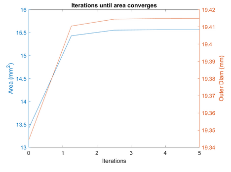
The final outer annular diameter is about 19.415mm, with an area of $15.564mm^2$, an increase of $.071mm$ and $2.154mm^2$ respectively.
The final aspect that is specific to Herald’s developmental injector are extra film cooling components. This was added so that we could be somewhat extra precautious in the first firing and testing of our engine. A separate fuel manifold was added above the main fuel manifold. This allows us to separately feed a fuel line into the film cooling manifold in order to vary it separate from the regenerative cooling fuel routing. We’ll be able to slowly turn down the film cooling flow in our tests if it isn’t fully needed. The current film cooling setup contains 32 1 mm diam holes that inject around the edge of the injector focused on cooling the walls of the combustion chamber.
The last integral aspect to our developmental injector is sensor ports. We ideally want to record the pressure from the combustion chamber and main fuel manifold as well as the temperature of the main fuel manifold. In our initial design this takes the form of 3 JIC - 4 ports sprinkled around the injector, with an attempt to not put them too close to each other to avoid a concentrated interruption to the flow in the main fuel manifold
Finally we arrive at the igniter and the decisions made around it. We decided to use a torch igniter for a few reasons. The main reason was due to its simpler reignition remotely. Igniting the engine from our bunker vs replacing a solid propellant igniter every engine fire was ideal. We also wanted the robustness a rapidly re-ignitable engine would give us in designing our self landing vehicle. It also is a feature everyone but the Russians builds into their engine, so figuring out the challenges inherent to the design and creating a working prototype was ideal to us.
The design challenge began when figuring out where to place the igniter. With a chamber diameter of around 3 inches, there is not much space available in the injector face. While we could have put it in the engine wall, we did not want to cause irregular cooling channel behavior in the side wall and figured the fuel manifold in the injector would better adapt to an igniter interrupting its flow. A quick contour was generated using RPA as a guideline for the igniter chamber. The igniter will function by two quarter inch feed lines of lox and Jet-A, with a port for a spark plug to ignite the propellants. Exact testing will inform us of the usability of our current design.
Post Warning: Now that you’ve read it all….This is the work of an amateur, I have done my best to create an accurate write up, but please take everything with a grain of salt. If you see any errors please reach out: max@maxoberg.dev . I will be striving to releases more versions when I find time as I fine tune this and can get other eyes on it.
Sources
-
Dressler, G., & Bauer, J. (2000). TRW Pintle Engine Heritage and Performance Characteristics. 36th AIAA/ASME/SAE/ASEE Joint Propulsion Conference and Exhibit. https://doi.org/10.2514/6.2000-3871 . ↩
-
Hutchinson, L. (2013, April 15). How NASA brought the monstrous F-1 “Moon rocket” engine back to life. Ars Technica. https://arstechnica.com/science/2013/04/how-nasa-brought-the-monstrous-f-1-moon-rocket-back-to-life/
-
Sakaki, K., Funahashi, T., Nakaya, S., Tsue, M., Kanai, R., Suzuki, K., Inagawa, T., & Hiraiwa, T. (2018). Longitudinal combustion instability of a pintle injector for a liquid rocket engine combustor. Combustion and Flame, 194, 115–127. https://doi.org/10.1016/j.combustflame.2018.04.017
-
Escher, D. W. (1996). Design and Preliminary Hot Fire and Cold Flow Testing of Pintle Injectors (Master’s Thesis). The Pennsylvania State University. BLOG Author Note: This paper is difficult as hell to get ahold of, I had to have it requested through my university library at the time as it is not available publicly digitally anywhere. It is really useful so reach out if you want advice on how to get it.
-
Kang, D., Han, S., Ryu, C., & Ko, Y. (2022). Design of pintle injector using kerosene-LOX as propellant and solving the problem of pintle tip thermal damage in hot firing test. Acta Astronautica, 201, 48–58. https://doi.org/10.1016/j.actaastro.2022.08.029
-
Bell, K. J., & Bergelin, O. P. (1957). Flow through annular orifices. Journal of Fluids Engineering, 79(3), 593–601. https://doi.org/10.1115/1.4013105
-
Zhou, R., & Shen, C. (2022). Experimental study on the spray characteristics of a pintle injector element. Acta Astronautica, 194, 255–262. https://doi.org/10.1016/j.actaastro.2022.02.019
-
Austin, B., & Heister, S. (2002). Characterization of pintle engine performance for nontoxic Hypergolic Bipropellants. 38th AIAA/ASME/SAE/ASEE Joint Propulsion Conference &Amp; Exhibit. https://doi.org/10.2514/6.2002-4029
-
Nardi, R., Perez, V., & Pimenta, A. (2015). Experiments with Pintle Injector Design and Development. 51st AIAA/SAE/ASEE Joint Propulsion Conference. https://doi.org/10.2514/6.2015-3810
-
Son, M., Yu, K., Koo, J., Kwon, O. C., & Kim, J. S. (2015). Effects of momentum ratio and Weber number on spray half angles of liquid controlled pintle injector. Journal of Thermal Science, 24(1), 37–43. https://doi.org/10.1007/s11630-015-0753-7
-
Son, M., Radhakrishnan, K., Koo, J., Kwon, O. C., & Kim, H. D. (2017). Design procedure of a movable pintle injector for Liquid Rocket Engines. Journal of Propulsion and Power, 33(4), 858–869. https://doi.org/10.2514/1.b36301